

nbc logo (2)
Office address
National Engineering Industries Ltd.
Khatipura Road Jaipur – 302006 Rajasthan, India
Phone Number

Toll Free: 1800 3000 6222
Telephone: +91 141 222 3221
Fax: +91 141 222 1926, 222 2259
CIN: U29130WB1946PLC013643

What Are the Top Types of RF Connector Adaptors?

Choosing the right RF connector adaptor can determine whether a signal remains clean, stable, and measurable. In practical testing, a poorly matched adaptor may create unexpected reflections, extra insertion loss, or a misleading measurement result. This is why engineers examine more than connector shape. They check impedance, operating frequency, shielding, durability, and the equipment’s interface before making a decision.

This guide explores the top types of Rf Connector Adaptors, including SMA, N-type, BNC, TNC, MCX, MMCX, and precision 2.92 mm options. Each design serves a different purpose. An SMA adaptor may suit compact laboratory equipment, while an N-type adaptor offers stronger outdoor performance. A BNC version provides fast bayonet coupling, which helps during repeated bench testing. However, convenience can hide limitations.

Small details matter.

A reliable selection process considers cable size, gender configuration, frequency range, and environmental exposure. It also reviews return loss, voltage standing wave ratio, and connector torque requirements. In my experience, technicians sometimes focus only on physical compatibility. That approach often fails when systems operate above several gigahertz. A connector may fit mechanically but perform poorly electrically. This article compares common adaptor types through practical applications, measurable specifications, and installation concerns. It also recognizes an uncomfortable truth: datasheets do not reveal every field problem. Real performance depends on assembly quality, calibration, contamination control, and repeated handling. Therefore, use these comparisons as guidance, not as a substitute for verified testing with suitable instruments.
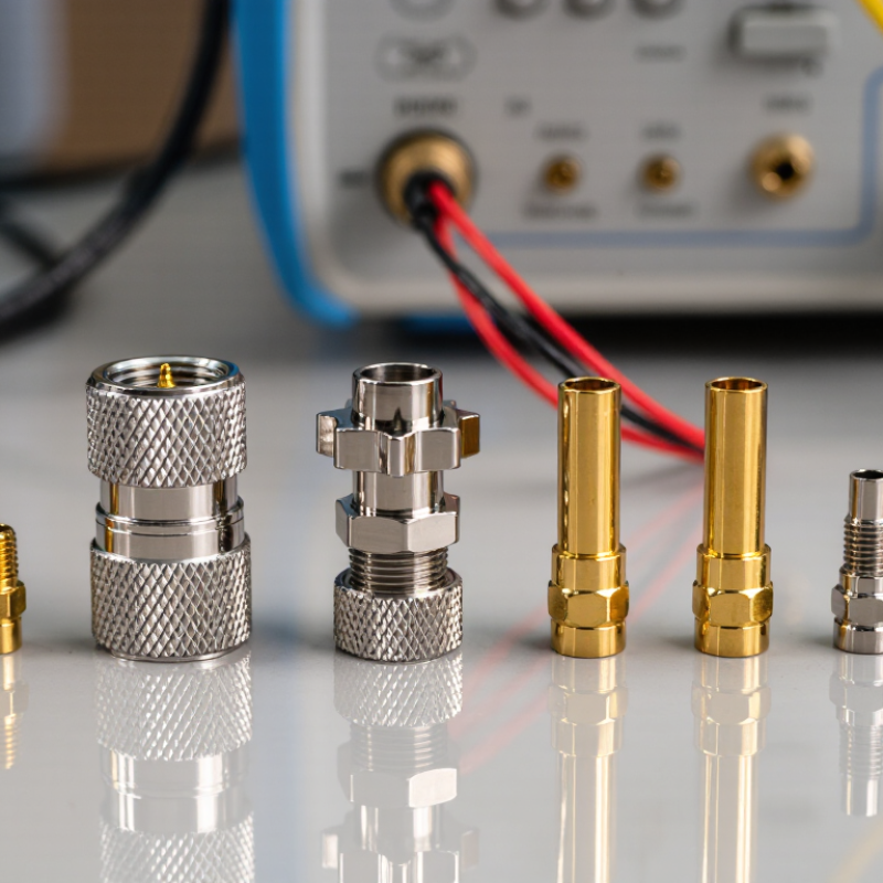
What Are the Top Types of RF Connector Adaptors?

Understanding RF Connector Adaptors and Their Basic Functions

RF connector adaptors bridge different connector interfaces while preserving a usable radio-frequency path. They are common in antennas, test equipment, coaxial cables, and wireless installations. An adaptor may change the connector series, gender, or mounting angle. It should not be treated as a simple mechanical joiner.

SMA adaptors suit compact, high-frequency equipment and usually use a 50-ohm system. N-type adaptors provide a larger threaded connection for outdoor antennas and stronger mechanical protection.

BNC adaptors use a quick bayonet coupling, making them practical for instruments that need frequent connection changes. TNC adaptors add threading to a BNC-style interface, improving resistance to vibration.

UHF adaptors remain useful in some legacy and lower-frequency systems, although their impedance control is less consistent. These are common choices, not universal answers.

The key function is controlled signal transfer. Check impedance before installation. A 50-ohm adaptor in a 75-ohm video path can create reflections and measurable loss. Frequency range matters too. A connector may fit perfectly but perform poorly at higher frequencies.

I have seen technicians overlook cable diameter and bend radius. That mistake can stress the adaptor and loosen the connection. Small detail. Big consequence. Keep mating surfaces clean, tighten threaded parts correctly, and avoid forcing mismatched interfaces.

Weather-exposed connections also need suitable sealing. Even careful selection cannot remove every loss, because each extra adaptor adds another transition.

Key Factors for Classifying RF Connector Adaptors

What Are the Top Types of RF Connector Adaptors?

RF connector adaptors are best classified by more than their outer shape. Their interface, impedance, frequency range, and installation method matter equally. Common types include plug-to-plug, jack-to-jack, and plug-to-jack adaptors. These gender combinations determine how cables or devices connect. Fit is not enough.

Impedance is another critical factor. A 50-ohm adaptor suits many test and communication systems, while 75-ohm versions often support video applications. Mixing impedance standards can increase signal reflections and measurement errors. Frequency rating also deserves attention. An adaptor designed for lower frequencies may perform poorly at microwave ranges. Body construction, shielding, and contact material influence durability and insertion loss. In field work, I have found that a mechanically secure connection can still produce unstable readings. The overlooked detail is often the adaptor, not the instrument.

Tips: Check the connector drawing before ordering. Confirm interface gender, impedance, operating frequency, and mounting style. Right-angle adaptors help in crowded panels, but they may add a small path change. Panel adaptors need firm hardware and suitable grounding. Measure twice. A clean interface is essential, although cleaning alone cannot correct a mismatched design. When specifications conflict, the application’s measured requirements should guide the choice.

What Are the Top Types of RF Connector Adaptors? - Key Factors for Classifying RF Connector Adaptors

Adaptor Type Primary Classification Typical Interface Arrangement Common Impedance Indicative Frequency Capability Main Technical Factors Typical Applications
Between-Series Adaptor Connector series SMA to N, BNC to TNC, or other dissimilar RF interfaces 50 Ω or 75 Ω, depending on the connected series DC to several GHz; limited by the lower-rated interface and construction Interface geometry, impedance transition, VSWR, insertion loss, and shielding Connecting test equipment, cables, antennas, and components with different connector families
In-Series Gender Adaptor Contact gender Male-to-male, female-to-female, or gender-changing versions within one connector series Usually 50 Ω; some connector families are 75 Ω DC to the rated frequency of the connector series Pin and socket alignment, mating compatibility, contact resistance, and mechanical durability Correcting incompatible gender combinations without changing the cable or equipment
Coaxial Series Adaptor Same-series connection Two connectors from the same family with different termination styles or genders Typically 50 Ω or 75 Ω Depends on connector family; precision versions can operate into the microwave range Nominal impedance, mating interface, coupling method, return loss, and power handling Extending, repairing, or reconfiguring coaxial cable assemblies
Right-Angle Adaptor Body orientation Ports positioned at approximately 90 degrees 50 Ω or 75 Ω Often lower than a straight adaptor at very high frequencies because of the bend geometry Electrical discontinuity, bend radius, insertion loss, package clearance, and cable strain Dense instrument panels, compact enclosures, antennas, and routing around obstacles
Bulkhead Adaptor Mounting method One RF interface on each side of a panel, wall, or enclosure 50 Ω or 75 Ω DC to the specified operating frequency of the adaptor Panel thickness, mounting hardware, sealing, grounding, shielding, and connector alignment Passing RF signals through equipment walls, racks, cabinets, and shielded enclosures
Flange-Mount Adaptor Mechanical mounting RF connector attached to a square, round, or custom mounting flange Commonly 50 Ω; other values are possible for specific systems From low frequency to microwave bands, subject to flange and connector design Flange dimensions, hole pattern, grounding, sealing, vibration resistance, and RF leakage Radar assemblies, communication equipment, antenna feeds, and modular RF hardware
Precision Test Adaptor Measurement accuracy Precision interfaces designed for repeatable connection to test ports Most commonly 50 Ω Typically from DC to multi-GHz or millimeter-wave frequencies Calibration repeatability, low VSWR, phase stability, connector wear, and dimensional accuracy Vector network analyzers, calibration kits, laboratory measurements, and RF verification
Waveguide-to-Coaxial Adaptor Transmission medium Rectangular or circular waveguide interface to a coaxial connector Coaxial side is commonly 50 Ω Determined by waveguide band, operating mode, and transition design Waveguide band, mode conversion, flange standard, VSWR, insertion loss, and power capacity Microwave test systems, radar equipment, antennas, filters, and high-frequency links
Coaxial-to-Twinaxial or Triaxial Adaptor Shield structure Conversion between coaxial and multi-conductor shielded interfaces System-dependent; commonly 50 Ω on the coaxial side Usually limited by the multi-conductor interface and shielding design Shield continuity, isolation, grounding scheme, crosstalk, impedance control, and safety requirements Data acquisition, instrumentation, low-noise measurement, and specialized signal systems
DC-Block Adaptor Electrical function Inline coaxial adaptor containing a series capacitor Usually 50 Ω or 75 Ω Specified by lower and upper cutoff frequencies; RF performance varies by design DC voltage isolation, capacitance, leakage, insertion loss, power rating, and maximum DC voltage Protecting instruments from unwanted bias voltage while passing an RF signal
RF Termination Adaptor Port termination Connector fitted with a matched internal load, commonly 50 Ω or 75 Ω 50 Ω or 75 Ω DC to the specified frequency range of the termination Return loss, power dissipation, thermal management, frequency flatness, and connector type Unused-port termination, system testing, calibration, and prevention of RF reflections
Low-PIM Adaptor Passive intermodulation High-quality RF adaptor designed for low passive intermodulation generation Commonly 50 Ω Often used from cellular bands through microwave frequencies, subject to design Contact materials, surface finish, torque control, cleanliness, RF current density, and PIM level Base-station systems, distributed antenna systems, and high-power wireless infrastructure
Note: Frequency capability, impedance, power handling, and performance values are representative classification ranges rather than universal limits. The exact rating must be confirmed from the adaptor’s mechanical drawing, datasheet, and mating-connector specifications. RF connectors with different nominal impedances should not be interconnected unless the system design explicitly permits it.

Common Types of RF Connector Adaptors by Connector Interface

What Are the Top Types of RF Connector Adaptors?

Common Types of RF Connector Adaptors by Connector Interface

RF connector adaptors are selected mainly by their connector interfaces, not by appearance alone. In field installations, I check the interface, gender, impedance, and rated frequency before choosing an adaptor. A neat fit can still produce poor return loss. Fit is not enough.

Threaded interfaces include SMA, N, TNC, and UHF types. They provide firm mechanical coupling for test equipment, antennas, and outdoor cable assemblies. SMA adaptors suit compact, higher-frequency connections, while N-type adaptors offer stronger weather resistance and handling strength. TNC combines threading with a compact body. UHF remains useful in lower-frequency systems, although its performance depends heavily on construction quality.

Bayonet interfaces, such as BNC, allow quick connection and removal during repeated measurements. They are practical for instruments, video systems, and general RF testing. Push-on interfaces, including MMCX, MCX, and SMB, save space inside compact equipment. However, their smaller bodies demand careful handling. I have seen loose push-on adaptors create intermittent readings after cable movement. That mistake is easy to miss.

Precision interfaces, including 2.92 mm and 2.4 mm types, support demanding microwave measurements. They require clean mating surfaces and controlled torque. Adaptor shape also matters. Straight, right-angle, bulkhead, and gender-changing versions solve different installation problems. I sometimes prefer a slightly larger adaptor when access is limited, even if the smaller option looks more elegant. Rechecking the datasheet remains essential.

What Are the Top Types of RF Connector Adaptors?

Common Types of RF Connector Adaptors by Connector Interface

This chart compares representative upper operating frequencies for common RF connector interfaces. Actual performance depends on connector design, impedance, cable construction, and installation quality. SMA and N interfaces are widely used for higher-frequency applications, while BNC, F, and UHF interfaces are commonly selected for lower-frequency systems.

How to Choose the Right RF Connector Adaptor for an Application

Choosing the right RF connector adaptor starts with the equipment, not the connector’s appearance.

Common options include SMA, N, BNC, TNC, F, and UHF types. Each supports different frequencies, mechanical designs, and installation needs. A field technician should confirm the connector series, gender, interface, and impedance before ordering. A small mismatch can create signal reflections, unstable measurements, or physical damage.

Check the system impedance carefully. Most radio and test applications use 50 ohms, while many video systems use 75 ohms. Never assume they are interchangeable.

Review the adaptor’s frequency range, voltage rating, power capacity, insertion loss, and return loss. For outdoor equipment, sealing, corrosion resistance, and temperature tolerance matter greatly. In tight panels, a right-angle adaptor may reduce cable stress. However, it can also add loss and another failure point. That trade-off is easy to overlook.

Tips:

Compare the datasheet with the actual equipment manual. Inspect the mating surfaces under good light. Verify thread type and contact condition. Use the recommended tightening method, but avoid excessive force. A torque wrench is helpful during repeatable testing. I have seen a correct-looking adaptor fail because its center contact was slightly recessed. Adaptor selection is not only about fit. It is about maintaining the entire RF path, from the source to the antenna or instrument. There is no perfect choice. Application details decide the reliable one.

Performance, Compatibility, and Installation Considerations

What Are the Top Types of RF Connector Adaptors?

RF connector adaptors usually fall into three practical groups: series adaptors, gender changers, and precision adaptors. Series adaptors join different interfaces, such as SMA to N-type. Gender changers solve plug-to-plug or jack-to-jack conflicts. Precision adaptors support higher-frequency testing, where tiny mechanical errors affect results. MarketsandMarkets’ 2024 RF connector analysis forecasts approximately 6% annual market growth through 2029. That trend reflects expanding wireless, aerospace, and test-equipment demand.

Performance depends on more than connector shape. Confirm 50-ohm or 75-ohm impedance before ordering. Check operating frequency, insertion loss, return loss, and voltage standing-wave ratio. A mismatched adaptor may create visible signal ripples on a network analyzer. IEC 61169 provides useful interface and dimensional guidance, but manufacturers may still apply different tolerances. That detail is easy to overlook. Installation also matters. Inspect both mating surfaces, remove dust, and align threads gently. Tighten to the specified torque, rather than relying on hand strength. Do not let a heavy cable hang from the adaptor.

Tips: Keep adaptors capped during storage. Use a calibrated torque wrench for repeatable connections. Record adaptor type, frequency range, and test date. A quick visual check can prevent hours of troubleshooting. In field work, I would also verify the cable’s bend radius, because the connector may be correct while the installation remains unstable.